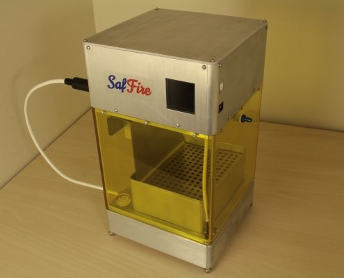
SafFire SLA 3D printer and laser engraver

Project Info:
The SafFire is a versatile 405nm/250mW laser projection system that features various sizes of accessories for SLA 3D printing. It provides unprecedented detail and accuracy due to utilizing automatically-tuned state-space control for the galvanometers and a special light-sensitive diode matrix for X/Y calibration. Designing a product such as this requires knowledge of embedded development, laser and galvanometer technology, control systems, screw threads and bearings, mesh file mathematics, and multithreaded graphical software.
LAVA LAB’S Contribution:
- Comparable product research
- Mechanical CAD drafting
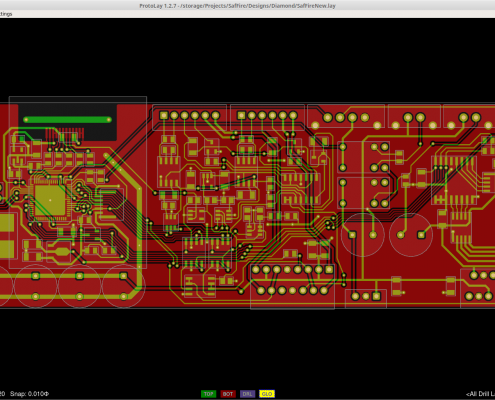
- Schematic design and PCB layout
- Galvanometer state-space control firmware
- Software for STL slicing and processing
- And more…see highlighted specialties below

Specialty: Lasers and Optics
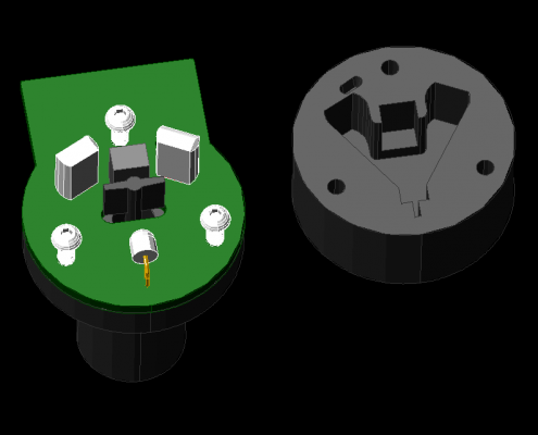
A 405nm/250mW laser diode lies at the heart of the SafFire stereolithography 3D printer. The driver PCB, shown at right, uses a bidirectional serial communication line (shared with the limit microswitch for the focus gears) to set the pulse current level and return temperature readings. Another TTL line allows for turning the diode on and off quickly. Having a variable current drive means being able to change voxel resolutions easily, which increases the usable print size range of the SafFire, in addition to the adjustable focus setting. Current level and focal plane adjustments can be made through the ProtoPart software.
SPECIALTY: MOTOR CONTROL
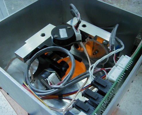
One of the main innovations of the SafFire is the use of a unique state-space control algorithm for the two galvanometers (at right). Most galvanometers use analog/digital PID control, but state-space results in better performance, particularly in regards to positioning error. In effect, state-space produces more accurate, smoother print results comparable to professional systems. Lava Labs also has experience with motors on the other side of the size spectrum, such as those used in electric vehicles, where sensored field-oriented control is a popular algorithm.


SPECIALTY: MECHANICAL DESIGN
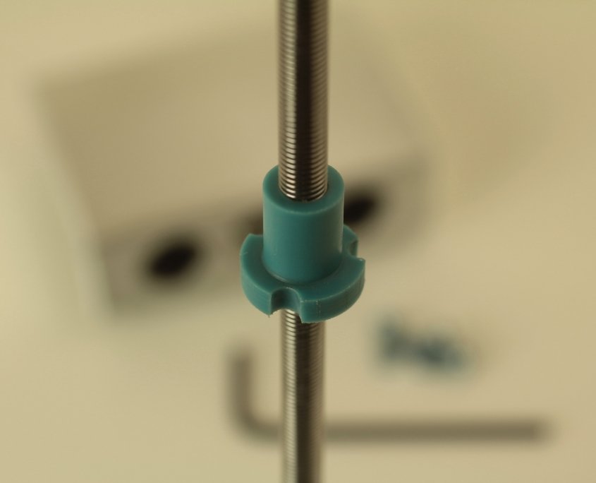
Mechanical design is an important aspect of almost every project in some form. For the SafFire, particular focus needed to be placed on the Z-motion components such as the custom Turcite A nut shown at right. This nut was cut on the lathe and later tapped to fit the available threaded motor shaft. Turcite A was chosen because of its low friction and good wear resistance compared to the original nut made of POM plastic. Another challenge with the SafFire was the molded UV-protective case. A dye had to be found that blocked 405nm but let through most other wavelengths. Six dyes were evaluated in cast acrylic and out of those, Solvent Yellow 93 was chosen for its superior safety performance.
SPECIALTY: AUTO-CALIBRATION
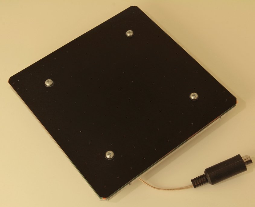
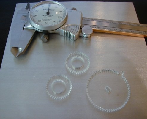
Since the SafFire lacks an expensive Z-theta lens, some method was needed to calibrate and linearize the galvanometer positions. An 11×11 diode matrix, shown at right, was developed to capture pulses of light from the laser beam on 0.5″ centers. After assembly, the SafFire is placed on top of the matrix and the galvanometer clamp screws are adjusted to roughly align the beam to the very center diode. A completely automated process then begins which scans first in a progressive “plus sign” pattern to find the approximate centers of the diodes, then follows up with two rounds of scanning on each of the 121 spots. The results are then put through a complex regression algorithm to find equations for the projection angles, which are used later.

SPECIALTY: ALGORITHMS
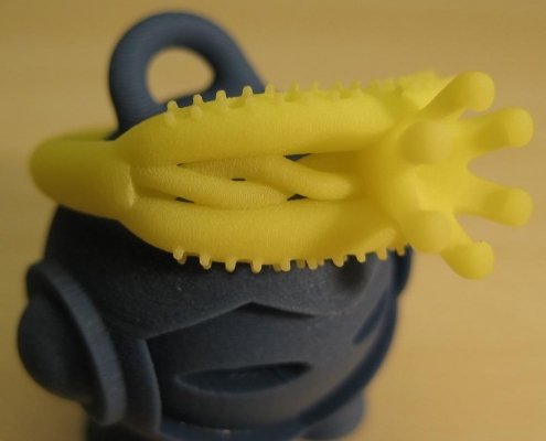
The SafFire, like most 3D printers, needed a way to convert the standard STL mesh file format into a digital voxel-based array. This is accomplished through a process called “slicing.” A custom algorithm was designed in ProtoPart (at right) to create a shell of voxels intersecting the mesh triangles. Many slicers suffer from errors when triangles are duplicated or overlapping; however, that is not an issue in this algorithm due to its thoughtful design. Unlike other slicers, most steps are also multithreaded for speed.
From start to launch; here are the product development steps.
1.
Discovery Phase
Schedule a 30 minute discovery meeting. We want to know everything about the future product.
2.
Development
Product development is all about having a dedicated team building your prototype, testing and refining until it is ready for manufacturing.
3.
Product launch and support
After the prototype has been designed built and tested our team of manufacturing experts will help you with everything needed to launch and support your new product.